Define every part
Include supplier, cavity, colour, finish and planned variants.
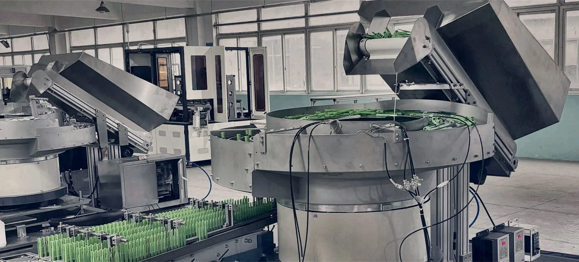
Technical guide · feeder selection
Compare vibratory bowl, centrifugal, step, flexible, linear and vision-guided component feeders by part behaviour, rate, orientation and changeover needs.
Selection principle
Choose the simplest technology that can meet the agreed accepted output across the real component range without unacceptable damage, intervention or changeover burden.
| Technology | Strong fit | Watch points | Guide |
|---|---|---|---|
| Vibratory bowl feeders for controlled component orientation | Screws, nuts, washers and inserts; Clips, pressings and small mouldings | Tangling, nesting and overlap behaviour; Track contact and cosmetic marking risk | View → |
| Centrifugal feeders for high-flow component presentation | Caps, closures and regular moulded parts; Robust components tolerant of dynamic movement | Dynamic stability and recirculation; Scuffing or surface-damage risk | View → |
| Step feeders for quiet, controlled component elevation | Long or heavier components; Parts that tangle in deep bulk | Lift geometry and stable rail presentation; Required final orientation after elevation | View → |
| Flexible feeders for changing products and difficult geometries | Multiple product variants; Delicate or cosmetically sensitive parts | Camera visibility and part overlap; Redistribution time and pick availability | View → |
| Hoppers, elevators and linear feeders for a complete feed path | Longer unattended running; Ergonomic low-level loading | Required autonomy and safe refill quantity; Maximum loading height and operator access | View → |
| Vision-guided feeding that verifies the part before hand-off | Orientation and rotational-position checks; Variant classification by visible features | What is objectively visible and measurable; Part position, focus, lighting and contrast | View → |
Include supplier, cavity, colour, finish and planned variants.
State face, leading feature, datum, pitch and height.
Measure accepted parts at hand-off over an agreed period.
Document buffers, signals, rejects, access and guarding.
Dedicated mechanical tooling can be rapid, robust and maintainable for one stable component. Flexible feeding becomes valuable when format variety, changeover frequency or complex orientation makes fixed tooling burdensome. Compare total operating value rather than purchase price alone.
| Decision factor | Dedicated bowl, step or centrifugal route | Flexible or vision-guided route |
|---|---|---|
| Product mix | Best suited to a stable part or tightly controlled family. | Useful where recipes and robot programs can cover genuine format variation. |
| Output | Can support high sustained flow when the part and tooling are proven. | Total cycle includes redistribution, imaging and robot picking. |
| Changeover | May need change tooling, adjustment or a dedicated feed path. | Can reduce mechanical change parts, but each format still needs validation. |
| Difficult behaviour | Tooling can reject incorrect attitudes repeatedly. | Vision can select pickable poses, provided overlap and presentation remain controlled. |
| Evidence required | Representative parts, required orientation, accepted sustained rate and the real downstream hand-off. | |
For tangling, nesting, static, tack or cosmetic surface risk, begin with the difficult-parts feeding guide. To set a realistic rate and queue brief, use the feeder rate and buffer planner.
Straight answers
Final suitability and performance are confirmed against the actual part and agreed trial criteria.
A flexible route may reduce mechanical change tooling where many variants are suitable for vision and robotic picking. A dedicated feeder can remain better for a stable high-volume component. Compare total cycle, changeover evidence, marking risk and downstream hand-off.
Sometimes. Variants must share enough geometry, handling behaviour and accepted presentation, or be managed through proven recipes and change parts. Every production variant should be included in the review and trial.
Start with downstream cycles per minute multiplied by parts per cycle, then add an agreed design margin. Specify sustained accepted output at the hand-off and enough accumulation for normal demand variation—not a short internal peak.
There is no universal answer. Tangling and nesting depend on bulk depth, geometry, friction and separation method. Representative trials may compare controlled elevation, bowl tooling, flexible presentation or pre-separation.
Start an application review
Share photographs or drawings, variants, material and finish, required orientation, target sustained output and details of the receiving machine.
Start with the required orientation, output and permitted handling effects. Provide representative components and identify changes expected across the product range. Compare the trial results, adjustment requirements and interface with the receiving machine, so the selected approach suits the component and production task together.
Related guidance: Rate & buffer planner · Integration guide