Agree the sample
Define quantity, variants, condition and production equivalence.
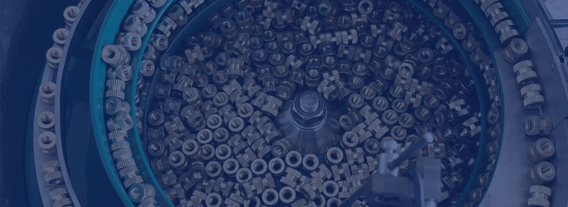
Application evidence · sample testing
Component feeder trials using representative production parts, agreed orientation, sustained output and interface criteria before system manufacture.
Why trial?
Friction, mould release, static, burrs, flexibility, nesting, tangling and normal dimensional variation often determine whether a feeding principle is reliable.
Define quantity, variants, condition and production equivalence.
Draw or photograph the required orientation, datum and quality.
Agree sustained rate, duration, replenishment and interventions.
Capture successful operation, rejects and residual risks.
A useful factory acceptance test records the agreed component set and test method before the run starts. Copy these points into the project specification:
Measure parts that reach the agreed hand-off in the accepted condition over a stated production-representative period. Include normal replenishment and downstream calls. Record interventions and rejected presentations separately, because an internal peak rate can conceal starvation or recirculation.
Use the component feeder rate and buffer planner to prepare an initial demand, margin, buffer and timed-test brief. The output is a planning estimate; the actual system performance still has to be proven with representative parts.
Straight answers
Final suitability and performance are confirmed against the actual part and agreed trial criteria.
The quantity depends on component size, target rate, duration, variants and recirculation. Estimate the accepted presentations required for the timed run, then allow additional parts for bulk loading, rejects, recirculation and every credible production variant.
Include every normal variation that could affect feeding. The worst credible combination may be more important than a large quantity from one easy batch.
Record the exact parts, accepted presentation, sustained output, duration, replenishment, interventions, rejects, surface condition, fault recovery and any agreed changeover.
No. A representative and well-defined trial reduces uncertainty, but installed services, downstream demand, contamination, operator practice and future part variation can still affect production.
Start an application review
Share photographs or drawings, variants, material and finish, required orientation, target sustained output and details of the receiving machine.