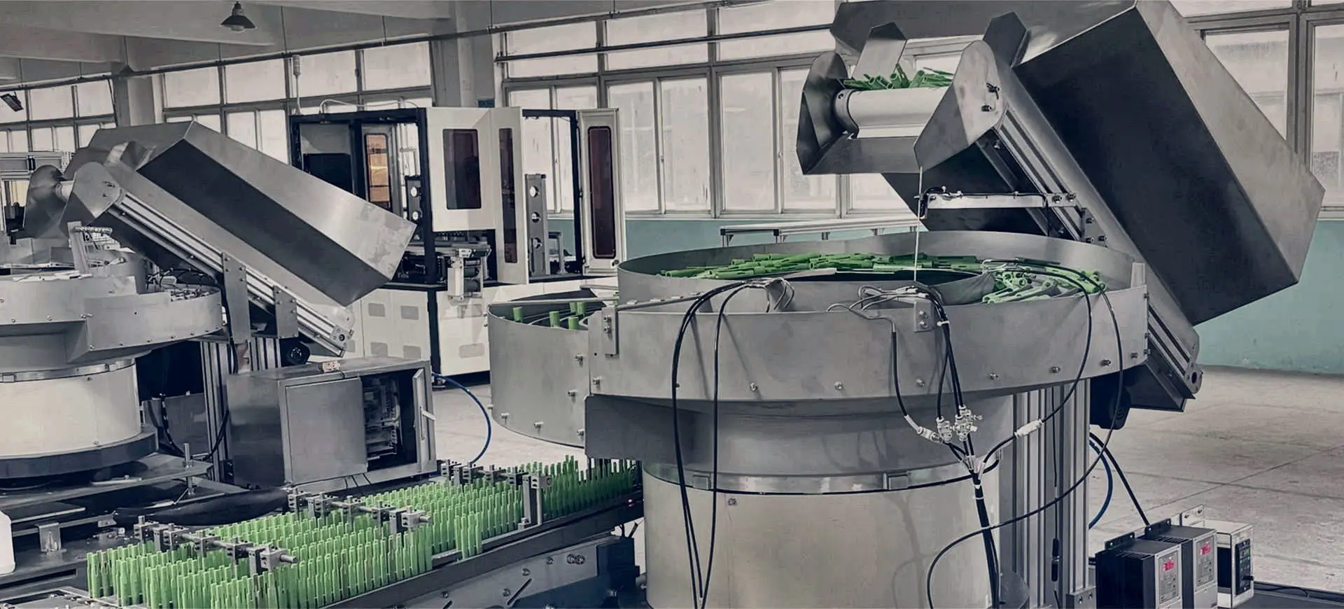
Bowl feeders and hopper elevators with green components on the feeding line.

Industry application · automated presentation

Electronics component feeding for precision assembly.

Precision feeding systems for electrical terminals, contacts, housings, connectors and small electronics components with vision and robot integration.

Typical components

Parts commonly assessed.

01

Contacts and terminals

02

Connector bodies

03

Pins, ferrules and inserts

04

Precision mouldings

Engineer the reliable hand-off.

Precision feeding systems for electrical terminals, contacts, housings, connectors and small electronics components with vision and robot integration. The complete scope may combine bulk storage, a bowl, centrifugal or step feeder, linear buffering, sensors, vision inspection, an escapement and the required PLC or robot signals.

Bowl feeders and hopper elevators with green components on the feeding line.

Information for selection

What to include in the brief.

  • Part drawings, photographs, dimensions, mass and finish
  • Every normal supplier, cavity, colour and material variant
  • Required orientation, datum, pitch and discharge height
  • Sustained rate, buffer demand and receiving-machine signals
  • Inspection, guarding, environment and access requirements

Where terminal attitude or presence must be verified, review vision-guided component feeding and define the ESD, queue and PLC boundaries in the integration brief.

Use the selection guide →

Straight answers

Common component-feeding questions.

Final suitability and performance are confirmed against the actual part and agreed trial criteria.

Can ESD-sensitive electronic components be fed?+

A system can be designed around an agreed electrostatic-discharge requirement using suitable contact materials, grounding, ionisation and environmental controls. The exact ESD boundary must be defined with the customer.

How are terminals and connectors checked for orientation?+

Mechanical tooling establishes stable presentation and sensors or vision can verify visible features, polarity, colour or orientation before the hand-off. Detectability must be proven with normal part variation.

Can one feeder run several connector sizes?+

Compatible families may share adjustable or change tooling. Wider variation often favours a flexible feeder with vision and robot recipes, but cycle time and changeover evidence should be compared.

Start an application review

Turn the part requirement into a defined feeding project.

Share photographs or drawings, variants, material and finish, required orientation, target sustained output and details of the receiving machine.

Call project team01844 617223