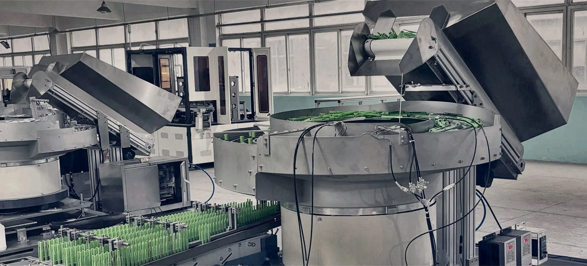
Bowl feeders and hopper elevators with green components on the feeding line.

Engineering guide · automated parts feeding

How component feeders turn loose parts into controlled presentation.

A component feeder converts randomly loaded parts into a repeatable, verified supply for assembly, packaging, inspection, counting or machine loading.

Engineering guidance · reviewed 25 August 2026 · UK-wide project support

How it works

Most component feeding systems perform six linked functions: bulk load, separate, orient, inspect, buffer and present. The useful output is the sustained number of accepted parts available at the final hand-off—not simply the movement speed inside the feeder.

The six stages of a feed path

  1. Bulk load: a hopper or operator supplies a controlled quantity of loose parts.
  2. Separate: vibration, rotary motion, steps or controlled surface movement reduce overlapping and tangling.
  3. Orient: tooling, guides, gravity or vision identify a usable attitude.
  4. Inspect: sensors or cameras verify presence, orientation or specified visible features.
  5. Buffer: a track or conveyor decouples short feed variations from machine demand.
  6. Present: an escapement or robot delivers one accepted part at the required datum and time.

How the main feeder principles differ

Vibratory bowls use controlled vibration and track tooling. Centrifugal feeders use rotary movement for high-flow presentation of suitable robust parts. Step feeders lift parts progressively from a low hopper. Flexible feeders redistribute parts on a surface so a camera and robot can locate pickable items.

Why part trials matter

Drawings show nominal geometry, but samples reveal friction, balance, flexibility, static, oil, burrs, mould variation and the way components interact in bulk. Trials should include credible variation and record sustained output, interventions, rejects and the condition of presented parts.

What happens at the end of the feeder?

The final transfer may be a gravity chute, linear track, conveyor, pneumatic tube, escapement or robot pick. This interface determines the outlet height, queue, sensors, control handshake and acceptance criteria, so it should be defined before the feeder is selected.

Specification detail

Component feeder types at a glance.

AreaWhat to defineWhy it matters
Vibratory bowlStable repeat parts with usable orientation features.Dedicated tooling, proven continuous flow.
CentrifugalSuitable robust parts needing smooth high flow.Rotary separation and continuous movement.
Step feederLonger, heavier or easily tangled components.Low loading height and reduced bowl vibration.
Flexible feederProduct families and difficult or changing geometry.Vision-guided recipes and reduced fixed tooling.
Linear / hopperBuffering, transport and controlled replenishment.Completes the feed path around the main orienter.

Engineering note: Final equipment suitability, output, safety, environmental performance and supplied scope must be established for the actual component, process and site.

Straight answers

Questions buyers and engineers ask.

These answers provide a practical starting point; representative parts and an agreed application review determine the final recommendation.

What does a component feeder do?+

It separates loose parts, establishes or verifies orientation and presents accepted components to the next production process at a controlled rate.

Is a parts feeder the same as a bowl feeder?+

No. A bowl feeder is one type of parts feeder. Other options include centrifugal, step, flexible, linear, hopper, magazine and application-specific presentation systems.

How is feeder speed measured?+

Measure sustained accepted parts at the agreed hand-off over a stated period, including normal replenishment and defined interventions.

Why do component feeders need tooling?+

Tooling uses part geometry to guide, reject, recirculate and present components. The drive creates movement; the tooling creates usable orientation.

Can a feeder inspect parts as well as orient them?+

Yes. Sensors or vision can check presence, orientation and agreed visible features before rejection or release to the next process.

Start an application review

Send the component. Define the hand-off. Compare the right feeder routes.

Share photographs or drawings, variants, material and finish, required orientation, target sustained output and details of the receiving machine.

Call project team01844 617223