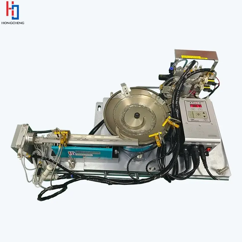
Metal bowl feeder with linear outfeed tooling, wiring and a control unit.

Industry application · automated presentation

Fastener feeding systems for automated assembly.

Automatic feeding and presentation systems for screws, nuts, washers, pins and inserts, including bowls, step feeders, tracks and escapements.

Typical components

Parts commonly assessed.

01

Screws and bolts

02

Nuts and captive nuts

03

Washers and rings

04

Pins, dowels and inserts

Engineer the reliable hand-off.

Automatic feeding and presentation systems for screws, nuts, washers, pins and inserts, including bowls, step feeders, tracks and escapements. The complete scope may combine bulk storage, a bowl, centrifugal or step feeder, linear buffering, sensors, vision inspection, an escapement and the required PLC or robot signals.

Automatic screw feeding systems and screw presenters

An automatic screw feeding system can orient and present screws to a fixed pick point, blow-feed head or automatic driver. A screw presenter for automated assembly must match the fastener head, shank, length range, finish, required datum and driver cycle—not just the nominal thread size.

Separate this application from bulk-material “screw feeders” used for powders. For assembly fasteners, review the complete automatic screw feeding system, including escape, hose or pick point, part-present confirmation and fault recovery.

Metal bowl feeder with linear outfeed tooling, wiring and a control unit.

Information for selection

What to include in the brief.

  • Part drawings, photographs, dimensions, mass and finish
  • Every normal supplier, cavity, colour and material variant
  • Required orientation, datum, pitch and discharge height
  • Sustained rate, buffer demand and receiving-machine signals
  • Inspection, guarding, environment and access requirements

Use the rate and buffer planner for the driver cycle, then test head, length, finish and every fastener variant through the trial and FAT method.

Use the selection guide →

Straight answers

Common component-feeding questions.

Final suitability and performance are confirmed against the actual part and agreed trial criteria.

Can screws be blow-fed through a tube?+

Suitable screws can be separated and transferred pneumatically, but shank length, head form, thread, orientation and the receiving driver or insertion tool must be assessed together.

How is double feeding prevented?+

An escapement isolates one fastener while mechanical geometry, part sensors and stroke or arrival confirmation detect an incorrect release. The method depends on the fastener and process risk.

Can oily fasteners be fed reliably?+

Potentially, but oil changes friction and can contaminate tooling and sensors. Trial samples should represent the production oil level, and access for routine cleaning should be included in the design.

Start an application review

Turn the part requirement into a defined feeding project.

Share photographs or drawings, variants, material and finish, required orientation, target sustained output and details of the receiving machine.

Specify the fastener at the receiving tool

A fastener can leave a feeder in the right direction and still be unsuitable for insertion. Define the condition at the screwdriver, riveting tool or assembly fixture so feeding and fastening have a shared acceptance point.

Distinguish presentation from successful assembly

For a screw, specify the leading end, head support and pickup location; for a washer or nut, define the face and centre location the tool needs. A part-present sensor does not by itself confirm a correct variant or a completed joint. Keep feeder acceptance and the assembly result as separate checks.

Assess the delivery route with the actual fastener

A fixed presentation point suits a tool that can collect from a known location. A transfer route must also accommodate the fastener geometry, length and surface condition without losing orientation. Do not assume that a route proved with one screw length will accept a longer shank, different head or captive washer unchanged.

Prevent mixed variants becoming a feeding problem

Record which differences affect tooling and which need an independent identification check. Include plausible look-alike fasteners in the trial. Define line clearance at changeover, including parts left in the hopper, track, transfer route and tool, rather than relying only on a changed recipe name.

Test the interrupted handover

Demonstrate a missing part, an occupied receiving point and an interrupted transfer under the agreed safe test procedure. Establish who owns the component after each step and what confirmation permits another release. A controlled stop with a clear recovery instruction is more useful than a second fastener being sent into an uncertain route.

Explore complete component feeding systems

Call project team01844 617223