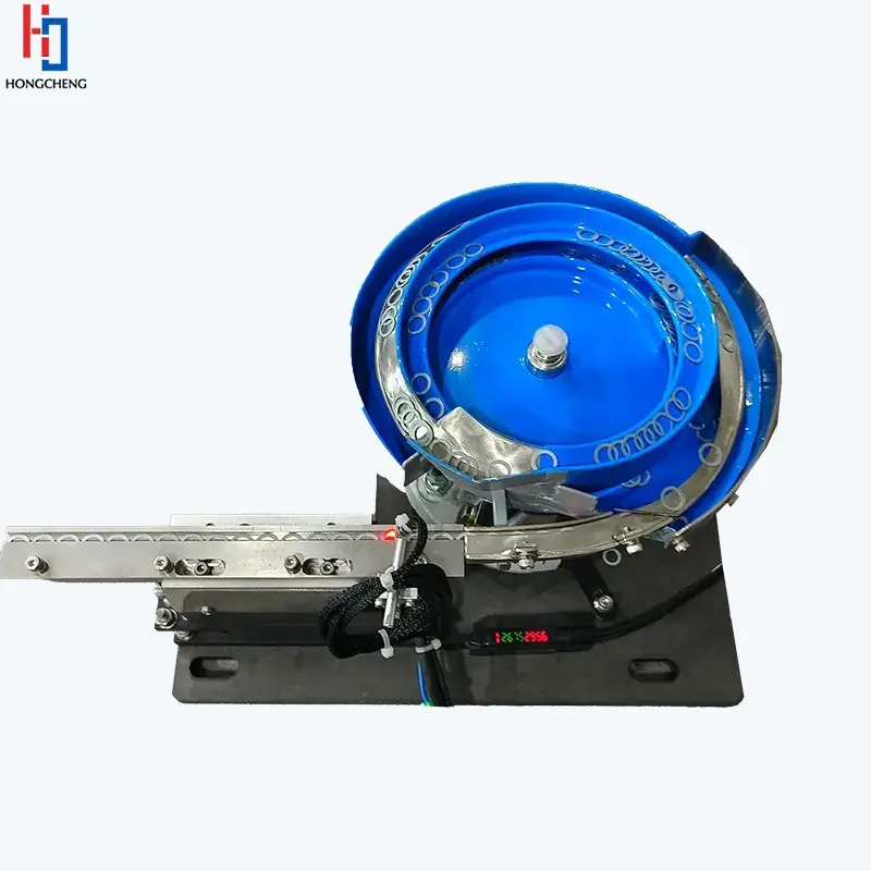
Blue-lined bowl feeder with ring-shaped components and a linear outfeed track.

Bespoke parts feeding · application engineered

Custom component feeders built around the part and the hand-off.

A custom component feeder combines the right feeding principle, part-specific tooling and a controlled interface to your assembly, packaging or inspection process.

Engineering guidance · reviewed 25 August 2026 · UK-wide project support

Direct answer

A custom component feeder is a part-specific system that separates, orients, buffers and presents loose production parts in the condition the next machine can use. It may combine a bowl, step, centrifugal or flexible feeder with tooling, sensors, escapements, controls and guarding.

When does a feeder need to be bespoke?

Standard drives and platforms are useful building blocks, but the working feed path is defined by the component. Geometry, centre of gravity, material, surface finish, variation, required orientation and the final pick or insertion point all influence the solution.

01 · PART

Shape, weight, friction, nesting and acceptable contact.

02 · OUTPUT

Required orientation, datum and sustained accepted rate.

03 · PROCESS

How the robot, fixture, driver or machine receives the part.

04 · EVIDENCE

Representative samples and measurable trial criteria.

What can the complete system include?

The correct scope may extend beyond the primary feeder. Bulk hoppers or elevators maintain product level; orienting tooling rejects incorrect attitudes; linear tracks provide accumulation; vision checks visible features; and an escapement releases one accepted component when the downstream machine calls.

Controls should manage demand, low level, track full, ready, fault and reset states. Mechanical layout must also allow safe access for loading, cleaning, recovery and planned maintenance.

How we reduce application risk

Sortation Solutions starts with production evidence rather than a catalogue assumption. We compare practical feeder routes, define what must be proven, coordinate representative trials and agree the interface before the final system scope is frozen.

This approach is suitable for small parts, clips, connectors, fasteners, mouldings, medical-device parts, electronics components, caps, closures and other repeat production components.

Specification detail

Information that shapes a custom feeder quotation.

AreaWhat to defineWhy it matters
ComponentMaterial, mass, dimensions, finish, tolerances and difficult features.Determines separation, contact and tooling behaviour.
PresentationRequired orientation, datum, pitch, queue and release method.Defines what counts as an accepted part.
PerformanceSustained accepted output and agreed test period.Prevents a misleading peak-speed comparison.
IntegrationOutlet height, space, controls, robot or machine interface.Makes the feeder usable in the real line.
EnvironmentCleanliness, static, oil, noise, guarding and access.Influences materials, covers and maintenance design.

Engineering note: Final equipment suitability, output, safety, environmental performance and supplied scope must be established for the actual component, process and site.

Straight answers

Questions buyers and engineers ask.

These answers provide a practical starting point; representative parts and an agreed application review determine the final recommendation.

Are all component feeders custom made?+

The primary technology may use standard modules, but the tooling, outlet, controls and interface are normally configured around the actual part and process.

How many samples are needed?+

The quantity depends on size, target rate, test duration, variation and whether parts can be recirculated. The sample plan is agreed after the initial review.

Can an existing feeder be incorporated?+

Possibly. Its condition, controls, capacity, tooling and interface must be reviewed against the new duty before reuse is recommended.

Can one system feed multiple variants?+

Compatible variants may share adjustable or change tooling. All proposed formats and the changeover method must be included in trials.

What should a factory acceptance test measure?+

It should measure sustained accepted parts at the agreed hand-off, using known samples and normal replenishment, with interventions, rejects and changeovers recorded.

Start an application review

Send the component. Define the hand-off. Compare the right feeder routes.

Share photographs or drawings, variants, material and finish, required orientation, target sustained output and details of the receiving machine.

Call project team01844 617223